


Yuheng Optics Co., Ltd.(Changchun)
News
- Innovation of Encoder Technology and Development of Industrial ApplicationsInnovation of Encoder Technology and Development of Industrial Applications 1. Theme selection and background With the advancement of Industry 4.0 and the rise of intelligent manufacturing, encoder technology, as a key component for precise measurement and control, plays a crucial role in the field of industrial automation. This article selects "Innovation of Encoder Technology and Development of Industrial Applications" as the theme, aiming to explore the latest progress of encoder technology and its widespread application in the industrial field, providing valuable information for the industry and academia. 2. Purpose and readership The main purpose of this article is to systematically introduce the innovative points of encoder technology, analyze its application cases in different industrial fields, and explore its future development trends. The target audience includes industrial engineers, automation control experts, scholars and graduate students in related fields, as well as general readers interested in encoder technology. 3. Article structure and outline Introduction: Introduce the importance of encoder technology and the purpose of writing this article. Technical background: Overview of the historical development, classification, and basic principles of encoder technology. Innovation analysis: Elaborate on the technical characteristics and innovations of new rotary encoders, angle encoders, linear encoders, and glass disc technologies. Application case: Through practical cases, demonstrate the application and effectiveness of encoder technology in different industrial fields. Future trends: Explore the development direction and potential application areas of encoder technology. Conclusion: Summarize the entire article and emphasize the driving role of encoder technology innovation in industrial development. 4. Content development and discussion In the content development section, this article will combine theory and practice to deeply analyze the innovative points and application cases of encoder technology. By comparing the advantages and disadvantages of traditional and new technologies, highlight the advantages of new encoder technology and its application value in the industrial field. 5. Language expression and style This article will adopt a clear, accurate, and objective language expression style, avoiding the use of overly professional or obscure terms. At the same time, emphasis is placed on logic and organization, enabling readers to easily understand the content of the article. 6. Argument and Evidence Support In order to enhance the persuasiveness of the article, relevant research literature, technical reports, and case studies will be cited as arguments and evidence support. By analyzing and evaluating these materials, provide readers with reliable information and evidence. 7. Conclusion and Inspiration In the conclusion section, this article will summarize the positive impact of encoder technology innovation on industrial application development, and point out its future development trends and potential challenges. At the same time, through the discussion and analysis in this article, we hope to provide readers with inspiration and thinking, and promote the further development and application of encoder technology.
2024 04/17
- Distinction between incremental encoder and absolute encoderDistinction between incremental encoder and absolute encoder Encoders can be divided into incremental pulse encoders: SPC and pulse encoders: APC based on the signal principle. Both are generally applied to the detection elements of speed control or position control systems. The distinction between incremental encoders and encoders. An encoder is a device that generates an information expression form according to a given code. It is a device that compiles and converts signals (such as bit streams) or data into signal forms that can be used for communication, transmission, and storage. It is a device that compiles and converts signals (such as bit streams) or data into signals that can be used for communication, transmission, and storage. Here, I recommend several encoders for you to facilitate your purchase. SM-D2100MPEG2 single-channel encoder is an easy-to-use, powerful MPEG-2 encoder. Supports various standard video and audio signals, including analog component S-VIDEO, analog composite video, and mono or analog stereo. The compressed data output format is ASI / SPI. Compression method MPEG-2MP @ ML, the encoder encodes and multiplexes the audio signal in real time and generates a DVB transmission stream. It is fully compliant with MPEG-2 and has extremely strong compatibility. Its volume is 1U chassis, and can be set and run completely offline through the front panel LCD screen. Its product features: 1. High-fidelity audio processing technology R / L channel, stereo input. 2. Support MPEG-2MP @ ML (4: 2: 0) encoding. 3. The output code rate is continuously adjustable, easy to use and flexible. 4. Rich output and input interface to realize free access. 5. SDT insertion. 6. The network management can be controlled locally and remotely. 7. LCD display, convenient and flexible operation. 8. High reliability design, stable operation.
2024 01/29
- The principle and use of incremental encoderThe principle and use of incremental encoder An encoder is a device that converts an angular displacement or a linear displacement into an electrical signal. According to the working principle, the encoder can be divided into two types: incremental (SPC) and absolute (APC). The incremental encoder converts the displacement into a periodic electrical signal, which is then converted into a counting pulse, and the number of pulses is used to represent the magnitude of the displacement. Here is some introduction to incremental encoders. 1. working principle The working principle of the photoelectric incremental encoder is as follows: the pulse code disc rotating together with the rotating shaft has a uniformly engraved grating, and a plurality of transparent sections and shading sections are evenly distributed on the code disc. Incremental encoders do not have a fixed starting zero. The output is a pulse proportional to the increment of the corner. A counter is required to count the number of pulses. Each time a light transmissive area is rotated, a pulse signal is sent, the current value of the counter is incremented by 1, and the count result corresponds to the increment of the corner. Incremental encoders are simple to manufacture, inexpensive, and sometimes used to measure absolute corners. 2. Incremental encoder classification (1) A single-channel incremental encoder has only one pair of optocouplers inside, and only one pulse sequence can be generated. (2) The AB phase encoder has two pairs of photocouplers inside, and outputs two sets of pulse sequences with a phase difference of 90°. The lead and lag relationship of the two pulses in the forward and reverse directions is just the opposite. As can be seen from the figure below, at the rising edge of the B-phase pulse, the level of the A-phase pulse is reversed when the forward and reverse are reversed. Therefore, using the AB-phase encoder, the PLC can easily recognize the direction of rotation of the shaft. When it is necessary to increase the accuracy of the measurement, the 4th frequency mode can be used, that is, the rising edge and the falling edge of the A and B phase waveforms respectively, and the resolution can be increased by 4 times, but the high frequency of the zui of the measured signal is correspondingly reduced. (3) In addition to the two pairs of optocouplers with dual-channel incremental encoders, the three-channel incremental encoder has one light-transmitting section in the other channel of the pulse code disc, one revolution per revolution, and output 1 One pulse, called the Z-phase zero pulse, is used as the system clear signal, or the origin of the coordinates to reduce the accumulated error of the measurement. The advantages of the incremental encoder are simple structure, long average life, strong anti-interference ability and high reliability, which is suitable for high-precision positioning control for continuous operation. The disadvantage is that the absolute position information of the shaft rotation cannot be output. 3. Encoder selection First, the type of encoder is selected according to the measurement requirements. The number of pulses per revolution of the incremental encoder is equal to the number of lines of its grating. The number of encoder lines should be determined according to the speed measurement or positioning requirements and the encoder speed. The encoder is mounted on the motor shaft or mounted on a shaft after deceleration. The encoder speed is very different. It should also be considered whether the high frequency of the zui of the pulse it emits is within the range allowed by the PLC's high-speed counter. 3. Coordination problem between encoder and PLC high-speed counter Taking the S7-200 as an example, when using a single-channel incremental encoder, the single-phase up/down counter mode (mode 0~5) of the high-speed counter can be selected, which can be subdivided into yes/no external direction input signals, with / No reset input and with/without start input signal. When using the AB phase encoder, the high-speed counter should select the A/B phase quadrature counter mode (modes 9 to 11), which can be used to count up during forward rotation and count down during reverse rotation. 4. How to judge whether the AB phase encoder is forward or reverse? The high-speed counter of the S7-200 uses the current count direction status bit in the SM area to indicate the direction of rotation of the encoder. If the period of the encoder output pulse is greater than twice the scan cycle time of the PLC, the direction of the encoder rotation can be judged by judging the 0, 1 state of the A phase pulse signal on the rising edge of the B phase pulse. Information from:
2024 01/12
- New Breakthroughs in Encoder Technology: High Precision and High Efficiency Becoming New StandardsNew Breakthroughs in Encoder Technology: High Precision and High Efficiency Becoming New Standards introduction With the rapid development of technology, encoders, as key equipment for data transmission and communication, have always received widespread attention for their technological innovation and application expansion. Recently, significant breakthroughs have been made in the field of encoders, with high-precision and high-efficiency encoders becoming a new industry standard. Background Introduction Encoder is a device that converts angular or linear displacement into electrical signals and is widely used in various mechanical and control systems. In recent years, with the rapid development of industries such as intelligent manufacturing and automation, encoders have put forward higher requirements in terms of accuracy, stability, and reliability. primary coverage Recently, a well-known technology company has launched a high-precision and high-efficiency encoder product. This product adopts advanced manufacturing processes and algorithms, achieving higher coding accuracy and faster response speed. Compared to traditional encoders, this product has lower energy consumption, longer service life, and higher stability. In addition, the encoder also supports multiple communication protocols and can seamlessly connect with other devices, providing users with more convenient solutions. At the same time, the encoder also has strong anti-interference ability and can operate stably in harsh working environments. case analysis To verify the performance of the encoder, we conducted on-site testing in a large manufacturing enterprise. The results show that the encoder can still maintain stable encoding accuracy under high-speed operation, greatly improving production efficiency. At the same time, its low-power design also saves a lot of energy costs for enterprises. Conclusion Summary With the launch of high-precision and high-efficiency encoder products, the encoder industry has entered a new stage of development. The successful application of this product not only enhances the overall level of encoder technology, but also injects new impetus into the development of industries such as intelligent manufacturing and automation. Personal opinions I believe that high-precision and high-efficiency encoder products will become the mainstream in the future market. With the continuous promotion of intelligent manufacturing and automation technology, as one of the core equipment, the improvement of encoder performance will directly promote the progress of the entire industry. At the same time, we should also pay attention to the sustainable development and environmental issues of encoder technology, ensuring that it not only creates value for society, but also conforms to the development concept of green environmental protection. Future outlook Looking ahead to the future, I look forward to greater breakthroughs in encoder technology in terms of accuracy, efficiency, stability, and more. At the same time, I also hope that the encoder industry can strengthen cooperation and communication with related fields such as intelligent manufacturing and automation, and jointly promote the rapid development of the entire industry. In addition, with the popularization and application of technologies such as the Internet of Things and big data, encoders, as key devices for data transmission and communication, will further expand and enrich their application scenarios.
2023 11/18
- Magnetic encodersEncoder Magnetic encoders are used in imaging systems such as X-ray, CT, PET, and MRI devices to replace analog potentiometers. MagRes encoders are available in single-turn and multi-turn versions, with standard 42- and 58-mm housings respectively. They have an optimum operating temperature of -20 to 85 degrees Celsius. The single-turn encoder weighs 120 grams and has a 12-bit resolution. The multi-turn encoder weighs 400 grams and has a 30-bit resolution. The device's zero-point adjustment is accompanied by a fan-shaped scan display and parallel output. Source of information: pack.cn
2023 09/11
- Ppt video encoder is not availablePpt video encoder is not available The reason why ppt video encoder is not available: The WMA audio file format you inserted is not compatible with PPT, although a codec is not available. The PPT is compatible with other playback software used on the computer, so it can play audio. Find compatible WMA audio files and use Windows Media Audio to compress sound files. It is usually published on the Internet and downloaded from the Internet. avi, asf, asx, mlv, mpg, wmv insertion method: 1. Using the "Insert Movie" command method in the "Insert" menu of PoerPoint is simple and common, and will not be described here. 2. Use the "Insert Object" command method in the "Insert" menu of PoerPoint 3. Use Insert Control Using this method must ensure that Windows MediaPlayer or RealPlayer player is installed in the system, first insert the video file as a control into the slide, and then modify the control properties to achieve the purpose of playing the video. Proceed as follows: (1) Run the PowerPoint program and open the slide that needs to be inserted into the video file. (2) Open the "View" menu, call up the "Control Toolbox" panel through the "Toolbar" sub-item, and select the "Other Controls" button to click. (3) In the open control options interface, select the "Windows Media Player" option, and then move the mouse to the PowerPoint slide editing area, draw a rectangular area of appropriate size, this rectangular area will automatically be converted to Windows Media Player player interface. (4) Use the mouse to select the playback interface, then click the right mouse button and select the "Properties" command from the pop-up shortcut menu to open the "Properties" window of the media playback interface. (5) In the "Properties" window, enter the detailed path (absolute path and relative path) and full file name of the video file to be inserted into the slide in the "URL" setting item, other options can be default. (6) During the slide show, you can control the video freely through the buttons of "play", "stop", "pause" and "adjust volume" and "progress bar" in the media player. How to insert video files such as rm, ra, rmvb Using Windows Media Player control can realize the playback of mpg, asf, avi, wmv and other video files, but it does not support the playback of RM video files, so how to realize the playback of RM video files in PowerPoint? If you use other video conversion software to convert the RM video file to AVI or MPG format file and then insert it, the speed is slow and the converted file size is also large, we can also use the "Control Toolbox" in PowerPoint to insert the RM format Video files, the method is as follows: 1. Open the PowerPoint slide file, and open the slide to be inserted into the video file. 2. Through the "View" menu, bring up the "Control Toolbox" panel, click the "Other Controls" button and select "RealPlayer G2" (at this time, the computer must have RealPlayer player installed), when the mouse becomes "+" At the time, use the left button to drag out a suitable size area (this area is the size of RealPlayer player) in the work area. 3. Right-click on this area, execute the "Properties" command in the pop-up shortcut menu, and enter the detailed path and full file name of the RM format file to be inserted after the "Source" item in the pop-up properties dialog box (must bring Suffix rm, for example, 8.rm, otherwise it cannot be displayed), select "false" after the "autostart" item to indicate that the video file will not be played automatically during playback. Other items are sufficient by default. Using the RM video file inserted in this way, displaying the realplay player interface during playback can easily perform operations such as volume, play, stop, pause, and progress dragging. Using this method must ensure that the realplayer player is installed in the system. The video files inserted by these two methods have a variety of operation buttons to choose from, and the playback process can be completely controlled by yourself, which is more convenient and flexible. This method is more suitable for the situation where pictures, texts and videos in PowerPoint courseware are on the same page. How to insert FLV video into PowerPoint: 1. Hyperlink method It is achieved by inserting a hyperlink of text or picture. This is very simple to make and is a method that everyone is very familiar with. However, it will be inconvenient and unintuitive to pop up a video playback window when using it, so I will not repeat it here. 2. Conversion method This method is actually using video conversion software to convert flv format video files into video formats like avi, mpg, etc. directly supported by PowerPoint, and then use PowerPoint to insert video menu commands to insert. The result of this processing essentially changes the format of the flv file, which is not only cumbersome to process, but also the video effect is greatly reduced due to the change in the video format of the processed video, while increasing the size of the video file. So this method is suitable for those who do not have high requirements for video quality, and the volume of video files in courseware is not limited. 3. Packing method This method is actually similar to the conversion method, except that the FLV video is imported into the Flash software and then exported as a SWF format file, and then the converted SWF format file is inserted and played in the PowerPoint using the Shockwave Flash Object control. The effect of this method, although the converted file volume is not as large as the avi and mpg files converted by the conversion method, the video effect will also be discounted. 4. Control method The plug-in method is to insert a Windows MediaPlayer control in PowerPoint and use this space to play flv video files, but to enable Windows Media Player to play flv video files, you first need to install a decoder for flv files on your computer. There are many decoders, I recommend a K-Lite Codec Pack. The installation of the decoder is very simple and will not be repeated here. Here is how to use the Windows Media Player control. (1) Open the slideshow where the video file needs to be inserted. Using Windows Media Player control can realize the playback of mpg, asf, avi, wmv and other video files, but it does not support the playback of RM video files, so how to realize the playback of RM video files in PowerPoint? If you use other video conversion software to convert the RM video file to AVI or MPG format file and then insert it, the speed is slow and the converted file size is also large, we can also use the "Control Toolbox" in PowerPoint to insert the RM format Video files, the method is as follows: (2) Open the "View" menu, call up the "Control Toolbox" panel through the "Toolbar" sub-item, and select the "Other Controls" button to click. (3) In the open control options interface, select the "Windows Media Player" option, and then move the mouse to the PowerPoint slide editing area, draw a rectangular area of appropriate size, this rectangular area will be automatically converted into WindowsMedia Player Player interface. (4) Use the mouse to select the playback interface, then click the right mouse button and select the "Properties" command from the pop-up shortcut menu to open the "Properties" window of the media playback interface. (5) In the "Properties" window, enter the detailed path and full file name of the flv video file that needs to be inserted into the slide at the "URL" setting item, other options can be defaulted. So far, during the slide show, you can play the inserted flv video file through the inserted Windows Media Player player control, and at the same time, you can also realize "play", "stop", "pause" and "adjust volume" for the video file. And the "progress bar" drag control. This method is not complicated to implement, and the inserted flv video file can achieve more control functions. The author recommends this method. 5. Player method Player method (that is, write a local FLV player similar to Google's web player googleplayer.swf in the Flsh editing environment, and then insert the Shockwave Flash Object plug-in in PowerPoint to play) The specific implementation steps are as follows: (1) Make FLV video player file (swf format file) The method of making FLV video player is not repeated here. Here we name the player made flvplayer.swf (2) Switch to the slide where you want to insert Flash animation. Open the "View" menu, bring up the "Control Toolbox" panel (3) Click "Other Controls" in the "Control Toolbox" to pop up the AcTIveX control window, find "Shobkwave Flash Object" in the control list and click, then the system will automatically close the control window. (4) Move the cursor to the editing area of the PowerPoint slide. The cursor changes to a "ten" shape. Press the left mouse button and drag to draw a rectangular frame of appropriate size. This rectangular area is the area where the Flash animation is played. (5) Click the right mouse button inside the rectangular frame, click "Properties" in the shortcut menu that appears, and the "Properties" window will pop up. (6) Enter flvplayer.swf directly in the text box on the right side of the "Movie" column in the "Properties" window? file = filename.FLV, "filename.FLV" is the file name of the FLV video we need to play. This means that the file name of the FLV video (if you are not in the same directory as the courseware, you need to add the detailed path) to the flvplayer.swf file through the parameter file. For other projects, just use the system default. Finally, close the "Properties" window and return to the PowerPoint slide editing window. This method is more complicated to operate, especially when you make the swf file format player file yourself. Interested readers can try it. Readers can choose to use the above methods according to their needs. Through the above discussion, we can insert these commonly used video files into PowerPoint, I hope to help everyone
2023 09/07
- The principle and use of incremental encoderThe principle and use of incremental encoder An encoder is a device that converts an angular displacement or a linear displacement into an electrical signal. According to the working principle, the encoder can be divided into two types: incremental (SPC) and absolute (APC). The incremental encoder converts the displacement into a periodic electrical signal, which is then converted into a counting pulse, and the number of pulses is used to represent the magnitude of the displacement. Here is some introduction to incremental encoders. 1. working principle The working principle of the photoelectric incremental encoder is as follows: the pulse code disc rotating together with the rotating shaft has a uniformly engraved grating, and a plurality of transparent sections and shading sections are evenly distributed on the code disc. Incremental encoders do not have a fixed starting zero. The output is a pulse proportional to the increment of the corner. A counter is required to count the number of pulses. Each time a light transmissive area is rotated, a pulse signal is sent, the current value of the counter is incremented by 1, and the count result corresponds to the increment of the corner. Incremental encoders are simple to manufacture, inexpensive, and sometimes used to measure absolute corners. 2. Incremental encoder classification (1) A single-channel incremental encoder has only one pair of optocouplers inside, and only one pulse sequence can be generated. (2) The AB phase encoder has two pairs of photocouplers inside, and outputs two sets of pulse sequences with a phase difference of 90°. The lead and lag relationship of the two pulses in the forward and reverse directions is just the opposite. As can be seen from the figure below, at the rising edge of the B-phase pulse, the level of the A-phase pulse is reversed when the forward and reverse are reversed. Therefore, using the AB-phase encoder, the PLC can easily recognize the direction of rotation of the shaft. When it is necessary to increase the accuracy of the measurement, the 4th frequency mode can be used, that is, the rising edge and the falling edge of the A and B phase waveforms respectively, and the resolution can be increased by 4 times, but the high frequency of the zui of the measured signal is correspondingly reduced. (3) In addition to the two pairs of optocouplers with dual-channel incremental encoders, the three-channel incremental encoder has one light-transmitting section in the other channel of the pulse code disc, one revolution per revolution, and output 1 One pulse, called the Z-phase zero pulse, is used as the system clear signal, or the origin of the coordinates to reduce the accumulated error of the measurement. The advantages of the incremental encoder are simple structure, long average life, strong anti-interference ability and high reliability, which is suitable for high-precision positioning control for continuous operation. The disadvantage is that the absolute position information of the shaft rotation cannot be output. 3. Encoder selection First, the type of encoder is selected according to the measurement requirements. The number of pulses per revolution of the incremental encoder is equal to the number of lines of its grating. The number of encoder lines should be determined according to the speed measurement or positioning requirements and the encoder speed. The encoder is mounted on the motor shaft or mounted on a shaft after deceleration. The encoder speed is very different. It should also be considered whether the high frequency of the zui of the pulse it emits is within the range allowed by the PLC's high-speed counter. 3. Coordination problem between encoder and PLC high-speed counter Taking the S7-200 as an example, when using a single-channel incremental encoder, the single-phase up/down counter mode (mode 0~5) of the high-speed counter can be selected, which can be subdivided into yes/no external direction input signals, with / No reset input and with/without start input signal. When using the AB phase encoder, the high-speed counter should select the A/B phase quadrature counter mode (modes 9 to 11), which can be used to count up during forward rotation and count down during reverse rotation. 4. How to judge whether the AB phase encoder is forward or reverse? The high-speed counter of the S7-200 uses the current count direction status bit in the SM area to indicate the direction of rotation of the encoder. If the period of the encoder output pulse is greater than twice the scan cycle time of the PLC, the direction of the encoder rotation can be judged by judging the 0, 1 state of the A phase pulse signal on the rising edge of the B phase pulse. Information from:
2023 09/07
- Application of 6-channel incremental encoder in intelligent textile machineThe balance of the textile mechanism of the intelligent textile machine is of great significance for improving the reliability of the work of the components and reducing the vibration, especially the noise in the textile production. In addition to the application of parts used in general machinery manufacturing, textile machines are also widely used in a series of special parts and mechanisms with unbalanced quality. In most cases, the parts with unbalanced quality are in the textile machine. The main body, and only intrinsic on the textile machine. The motor is an intrinsic component of a smart-controlled textile machine. The monitoring of the motor shaft is an important technology. The Rep-Avago's 48mm 6-channel incremental encoder from Shenzhen Shiqiang can meet the application of the textile industry. The 6-channel incremental encoder is a high-precision metering grating as a detecting component, and converts the input angular position information into a corresponding pulse or digital code detecting device by photoelectric conversion technology. Incremental encoders consist of LED light sources, grating pairs, optoelectronic receivers, spindles, electronic processing circuits and more. The grating pair is composed of a main grating code disc and an indicating grating as a main detecting unit of the photoelectric encoder; the code disc is fixed on the main shaft, and the other components are fixed as the main shaft rotates synchronously. The 6-Channel Incremental Encoder 48T2 Series is a high performance, low cost 6 channel incremental optical encoder. The chip is suitable for small and medium-sized servo motors and uses a transmissive principle, which can be applied at -25 ° C to 100 ° C. The 48T2 series encoder signal output has (A&B) two quadrature signals and zero signal (I), as well as motor magnetic pole position signals U, V, W. The encoder has excellent switching accuracy and high response speed, which makes the coding It is one of the ideal choices for servo motor position detection of textile machines. 6-channel incremental encoder 48T2 series features : 1) Six-channel integrated output (ABI, UVW) 2) Two orthogonal signals and zero signal output (A, B, I) 3) The zero signal output is 180 degrees or 360 degrees. 4) RS-422 long-line drive output, 8-wire or 14-wire optional 5) Maximum support 2500CPR 6) Operating temperature -25 ° C to 100 ° C 7) Response frequency of 250Khz 8) Support voltage DC+5V 9) RoHS compliant 10) Sealability is IP40 6-channel incremental encoder 48T2 series application project: • Servo motor, DC brushless motor • Textile machinery • CNC machine tools • Factory automation • Elevator About Shiqiang Founded in 1993, Shiqiang Advanced includes Avago, Renesas Electronics, Silicon Labs, Rogers, Melexis, Infineon, Acam, Alliance, Micrel, Littelfuse, NEMICON, EMC & RF Labs, EPSON, Cpyress, Vincotech, SMI, Ricoh Microelectronics, Keysight and other world-renowned semiconductor companies and test and measurement instruments companies are important distributors in Greater China, and are also important suppliers to many electronics manufacturing and R&D companies. In the communications, consumer and automotive electronics sectors, more emerging markets such as the Internet of Things, Internet of Vehicles, Wearables, and Smart Mobile Devices bring more cutting-edge technologies and innovative products. As a technology-driven distribution company, Shiqiang also has a mature technical support team and system service processes to provide customers with new product introduction, rapid sample, application consulting, solution and software design, development environment, after-sales and logistics. Professional services. In 2014, Shiqiang had annual sales of US$232 million and has 17 branches and offices throughout the country, with nearly 500 employees.
2023 08/30
- Decarburization pump incremental transformationDecarburization pump incremental transformation Abstract: Through the reformation of centrifugal pump impeller structure, increasing the flow, raising the lift, meeting the production requirements. Key words: Centrifugal pump retrofit flow rate increase The decarburization system in our workshop adopts the hot potash method to remove CO2 from the low volatility gas to provide a qualified hydrogen-nitrogen mixture for ammonia synthesis and at the same time provides CO2 gas with purity greater than 98% for urea production. The solution circulation mainly by decarbonization pump to provide energy. Over the years, the system load is low, the required flow is less than 200m3 / h, far less than the design capacity of the pump 480m3 / h. In order to reduce power consumption, in 92 years its impeller cylindrical cutting, the effect is good. However, since the first phase of the 81 August fertilizer program was put into operation in 1999, the required flow rate increased to 240 m3 / h. According to the reconstruction team's calculation, the large pump impeller was restored to the original large impeller, basically meeting the production requirements at that time. When the second phase of fertilizer "8 · 13" was put into operation in 2001, the required flow rate increased to 280m3 / h. At this moment, the problem is exposed, the flow of large pump can not be increased any more, the liquid-liquid phenomenon appears in the atmospheric tower, Production is very unstable, the load is difficult to increase. In order to solve this bottleneck that restricts production, the workshop and the maneuver department formed a special research personnel. improvement measures Pump volute erosion wear problems, due to the difficulty of repairing, do not deal with. In order to reduce the backflow, strictly control the impeller wear ring and pump wear ring gap at 0.50 ~ 0.68mm, but at the same time on the pump shaft stiffness, straightness and the manufacturers conducted a coordinated, in strict accordance with the technical requirements. Such as quenching and tempering should be done to the regular manufacturers, and a written report. After each overhaul, should use the dial indicator to find the correct control tolerance is less than 0.05mm, to ensure that the pump shaft concentric with the motor shaft. Reasonable deployment of system heat balance in production, as far as possible to reduce the temperature of imported lye, the maximum shall not exceed 108 ℃. Aiming at the impeller structure problem, Yangzhou Lianxing Pump Co., Ltd. commissioned by the Department of Mechanical Engineering to recalculate the design without changing the assembly size in two steps. The first step is to improve the blade involute, Welded type, eliminating the bumpy inner surface after casting defect. The second step in the intensity of the allowable range of accounting, the appropriate reduction of the thickness of the blade and the front and rear cover, increasing the size of the entrance. Transformation effect After the new impeller put into operation, the operation is smooth and the effect is good. After the first improvement of the impeller structure, the flow rate is increased from 240m3 / h to 270m3 / h, basically meeting the production requirements. After the second improvement, the flow rate is increased To 310m3 / h, higher than the 280m3 / h currently required to sustain high-load production. In the case of unstable production, it is easy to adjust the process, increase the flexibility of operation, increase the capacity of absorbing CO2, eliminate the phenomenon of blocking the two towers and eliminate a big bottleneck of the restriction of the workshop control load. Foundation.
2023 08/24
- EncoderEncoder Magnetic encoders are used in imaging systems such as X-ray, CT, PET, and MRI devices to replace analog potentiometers. MagRes encoders are available in single-turn and multi-turn versions, with standard 42- and 58-mm housings respectively. They have an optimum operating temperature of -20 to 85 degrees Celsius. The single-turn encoder weighs 120 grams and has a 12-bit resolution. The multi-turn encoder weighs 400 grams and has a 30-bit resolution. The device's zero-point adjustment is accompanied by a fan-shaped scan display and parallel output. Source of information: pack.cn
2023 08/23
- Incremental encoder phase alignment - Database & Sql Blog ArticlesIncremental encoder phase alignment - Database & Sql Blog Articles Factory direct 0805 red light quality absolutely guaranteed price absolute advantage Programmable Package SG-8018CA(SG7050C) 0.67M~170M AD brand ADUM1402ARWZ special treatment original imported absolutely original The output signal of the incremental encoder is a square wave signal, which can be divided into an incremental encoder with a commutation signal and a conventional incremental encoder. The ordinary incremental encoder has a two-phase orthogonal square wave. Pulse output signals A and B, and zero-bit signal Z; Incremental encoder with commutation signal, in addition to the ABZ output signal, also has the number of revolutions per revolution of the electronic commutation signal with 120 degrees difference from each other and the motor rotor The number of magnetic poles is the same. The alignment of the phase of the UVW electronic commutation signal with the incremental encoder with the commutation signal and the phase of the rotor pole, or the phase of the electrical angle are as follows: 1. Use a DC power supply to pass the DC winding of the motor to a DC current less than the rated current, U in, V out, to orient the motor shaft to an equilibrium position; 2. Observe the U phase signal and Z signal of the encoder with an oscilloscope; adjust the relative position of the encoder shaft and the motor shaft, or the relative position of the encoder housing and the motor housing, according to the convenience of operation; 3. While adjusting, observe the U-phase signal edge of the encoder and the Z signal until the Z signal is stable at a high level (in this case, the normal state of the Z signal is low), and lock the encoder to the motor. Positional relationship; Reverse the motor shaft back and forth. After releasing the hand, if the motor shaft is free to return to the equilibrium position each time, the Z signal can be stabilized at a high level, and the alignment is effective. After removing the DC power supply, verify as follows: Observe the U phase signal of the encoder and the UV back EMF waveform of the motor with an oscilloscope; When the motor shaft is rotated, the rising edge of the U-phase signal of the encoder coincides with the zero-crossing point of the UV line back EMF waveform of the motor, and the Z signal of the encoder also appears at this zero-crossing point. The above verification method can also be used as an alignment method. It should be noted that at this time, the phase zero point of the U-phase signal of the incremental encoder is aligned with the phase zero point of the motor UV back-EM potential. Since the U-electrode potential of the motor is different from the UV-line back-EM potential by 30 degrees, After this alignment, the phase zero point of the U-phase signal of the incremental encoder is aligned with the -30-degree phase point of the opposite potential of the motor U, and the phase angle of the motor electrical angle is the same as the phase of the potential waveform of the U opposite, so the incremental coding is performed at this time. The phase zero of the U-phase signal of the device is aligned with the -30 degree point of the electrical phase angle of the motor. ^ Some servo companies are accustomed to directly aligning the zero point of the encoder's U-phase signal with the zero point of the motor's electrical angle. To achieve this, you can: 1. Connect three stars with the same resistance to form a star, and then connect the three resistors connected to the star to the UVW three-phase winding leads of the motor; 2. Observing the midpoint of the U-phase input of the motor and the star-shaped resistor with an oscilloscope, the approximate U-potential waveform of the motor can be approximated; Adjusting the relative position of the encoder shaft and the motor shaft, or the relative position of the encoder housing and the motor housing, depending on the ease of operation; 3. While adjusting, observe the rising edge of the U-phase signal of the encoder and the zero-crossing point of the potential waveform of the motor U from low to high, and finally make the rising edge and the zero-crossing point coincide, lock the relative position relationship between the encoder and the motor, and complete the alignment. . Since the conventional incremental encoder does not have UVW phase information, and the Z signal can only reflect one point within one circle, and does not have direct phase alignment potential, it is not a topic of discussion. Phase Alignment of Absolute Encoders The phase alignment of absolute encoders is not much different for single and multiple turns. In fact, the phase of the detected phase of the encoder and the electrical angle of the motor are aligned within one turn. Early absolute encoders gave the highest level of the single-turn phase as a separate pin. With this level of 0 and 1 flipping, the phase alignment of the encoder and motor can also be achieved as follows: Use a DC power supply to pass the UV winding of the motor to a DC current less than the rated current, U in, V out, to orient the motor shaft to an equilibrium position; 4. Observe the highest count bit level signal of the absolute encoder with an oscilloscope; Depending on the ease of operation, adjust the relative position of the encoder shaft and the motor shaft, or adjust the relative position of the encoder housing and the motor housing while observing the transition edge of the highest count bit signal until the jump edge appears accurately in the motor. The relative positional relationship between the encoder and the motor is locked at the directional balance position of the shaft; 5. Reverse the motor shaft back and forth. After the hand is released, if the motor shaft is free to return to the equilibrium position each time, the jump edge can be accurately reproduced, and the alignment is effective.
2023 08/11
- Incremental encoder phase alignment - Database & Sql Blog ArticlesIncremental encoder phase alignment - Database & Sql Blog Articles Factory direct 0805 red light quality absolutely guaranteed price absolute advantage Programmable Package SG-8018CA(SG7050C) 0.67M~170M AD brand ADUM1402ARWZ special treatment original imported absolutely original The output signal of the incremental encoder is a square wave signal, which can be divided into an incremental encoder with a commutation signal and a conventional incremental encoder. The ordinary incremental encoder has a two-phase orthogonal square wave. Pulse output signals A and B, and zero-bit signal Z; Incremental encoder with commutation signal, in addition to the ABZ output signal, also has the number of revolutions per revolution of the electronic commutation signal with 120 degrees difference from each other and the motor rotor The number of magnetic poles is the same. The alignment of the phase of the UVW electronic commutation signal with the incremental encoder with the commutation signal and the phase of the rotor pole, or the phase of the electrical angle are as follows: 1. Use a DC power supply to pass the DC winding of the motor to a DC current less than the rated current, U in, V out, to orient the motor shaft to an equilibrium position; 2. Observe the U phase signal and Z signal of the encoder with an oscilloscope; adjust the relative position of the encoder shaft and the motor shaft, or the relative position of the encoder housing and the motor housing, according to the convenience of operation; 3. While adjusting, observe the U-phase signal edge of the encoder and the Z signal until the Z signal is stable at a high level (in this case, the normal state of the Z signal is low), and lock the encoder to the motor. Positional relationship; Reverse the motor shaft back and forth. After releasing the hand, if the motor shaft is free to return to the equilibrium position each time, the Z signal can be stabilized at a high level, and the alignment is effective. After removing the DC power supply, verify as follows: Observe the U phase signal of the encoder and the UV back EMF waveform of the motor with an oscilloscope; When the motor shaft is rotated, the rising edge of the U-phase signal of the encoder coincides with the zero-crossing point of the UV line back EMF waveform of the motor, and the Z signal of the encoder also appears at this zero-crossing point. The above verification method can also be used as an alignment method. It should be noted that at this time, the phase zero point of the U-phase signal of the incremental encoder is aligned with the phase zero point of the motor UV back-EM potential. Since the U-electrode potential of the motor is different from the UV-line back-EM potential by 30 degrees, After this alignment, the phase zero point of the U-phase signal of the incremental encoder is aligned with the -30-degree phase point of the opposite potential of the motor U, and the phase angle of the motor electrical angle is the same as the phase of the potential waveform of the U opposite, so the incremental coding is performed at this time. The phase zero of the U-phase signal of the device is aligned with the -30 degree point of the electrical phase angle of the motor. ^ Some servo companies are accustomed to directly aligning the zero point of the encoder's U-phase signal with the zero point of the motor's electrical angle. To achieve this, you can: 1. Connect three stars with the same resistance to form a star, and then connect the three resistors connected to the star to the UVW three-phase winding leads of the motor; 2. Observing the midpoint of the U-phase input of the motor and the star-shaped resistor with an oscilloscope, the approximate U-potential waveform of the motor can be approximated; Adjusting the relative position of the encoder shaft and the motor shaft, or the relative position of the encoder housing and the motor housing, depending on the ease of operation; 3. While adjusting, observe the rising edge of the U-phase signal of the encoder and the zero-crossing point of the potential waveform of the motor U from low to high, and finally make the rising edge and the zero-crossing point coincide, lock the relative position relationship between the encoder and the motor, and complete the alignment. . Since the conventional incremental encoder does not have UVW phase information, and the Z signal can only reflect one point within one circle, and does not have direct phase alignment potential, it is not a topic of discussion. Phase Alignment of Absolute Encoders The phase alignment of absolute encoders is not much different for single and multiple turns. In fact, the phase of the detected phase of the encoder and the electrical angle of the motor are aligned within one turn. Early absolute encoders gave the highest level of the single-turn phase as a separate pin. With this level of 0 and 1 flipping, the phase alignment of the encoder and motor can also be achieved as follows: Use a DC power supply to pass the UV winding of the motor to a DC current less than the rated current, U in, V out, to orient the motor shaft to an equilibrium position; 4. Observe the highest count bit level signal of the absolute encoder with an oscilloscope; Depending on the ease of operation, adjust the relative position of the encoder shaft and the motor shaft, or adjust the relative position of the encoder housing and the motor housing while observing the transition edge of the highest count bit signal until the jump edge appears accurately in the motor. The relative positional relationship between the encoder and the motor is locked at the directional balance position of the shaft; 5. Reverse the motor shaft back and forth. After the hand is released, if the motor shaft is free to return to the equilibrium position each time, the jump edge can be accurately reproduced, and the alignment is effective.
2023 08/10
- The principle and use of incremental encoderThe principle and use of incremental encoder An encoder is a device that converts an angular displacement or a linear displacement into an electrical signal. According to the working principle, the encoder can be divided into two types: incremental (SPC) and absolute (APC). The incremental encoder converts the displacement into a periodic electrical signal, which is then converted into a counting pulse, and the number of pulses is used to represent the magnitude of the displacement. Here is some introduction to incremental encoders. 1. working principle The working principle of the photoelectric incremental encoder is as follows: the pulse code disc rotating together with the rotating shaft has a uniformly engraved grating, and a plurality of transparent sections and shading sections are evenly distributed on the code disc. Incremental encoders do not have a fixed starting zero. The output is a pulse proportional to the increment of the corner. A counter is required to count the number of pulses. Each time a light transmissive area is rotated, a pulse signal is sent, the current value of the counter is incremented by 1, and the count result corresponds to the increment of the corner. Incremental encoders are simple to manufacture, inexpensive, and sometimes used to measure absolute corners. 2. Incremental encoder classification (1) A single-channel incremental encoder has only one pair of optocouplers inside, and only one pulse sequence can be generated. (2) The AB phase encoder has two pairs of photocouplers inside, and outputs two sets of pulse sequences with a phase difference of 90°. The lead and lag relationship of the two pulses in the forward and reverse directions is just the opposite. As can be seen from the figure below, at the rising edge of the B-phase pulse, the level of the A-phase pulse is reversed when the forward and reverse are reversed. Therefore, using the AB-phase encoder, the PLC can easily recognize the direction of rotation of the shaft. When it is necessary to increase the accuracy of the measurement, the 4th frequency mode can be used, that is, the rising edge and the falling edge of the A and B phase waveforms respectively, and the resolution can be increased by 4 times, but the high frequency of the zui of the measured signal is correspondingly reduced. (3) In addition to the two pairs of optocouplers with dual-channel incremental encoders, the three-channel incremental encoder has one light-transmitting section in the other channel of the pulse code disc, one revolution per revolution, and output 1 One pulse, called the Z-phase zero pulse, is used as the system clear signal, or the origin of the coordinates to reduce the accumulated error of the measurement. The advantages of the incremental encoder are simple structure, long average life, strong anti-interference ability and high reliability, which is suitable for high-precision positioning control for continuous operation. The disadvantage is that the absolute position information of the shaft rotation cannot be output. 3. Encoder selection First, the type of encoder is selected according to the measurement requirements. The number of pulses per revolution of the incremental encoder is equal to the number of lines of its grating. The number of encoder lines should be determined according to the speed measurement or positioning requirements and the encoder speed. The encoder is mounted on the motor shaft or mounted on a shaft after deceleration. The encoder speed is very different. It should also be considered whether the high frequency of the zui of the pulse it emits is within the range allowed by the PLC's high-speed counter. 3. Coordination problem between encoder and PLC high-speed counter Taking the S7-200 as an example, when using a single-channel incremental encoder, the single-phase up/down counter mode (mode 0~5) of the high-speed counter can be selected, which can be subdivided into yes/no external direction input signals, with / No reset input and with/without start input signal. When using the AB phase encoder, the high-speed counter should select the A/B phase quadrature counter mode (modes 9 to 11), which can be used to count up during forward rotation and count down during reverse rotation. 4. How to judge whether the AB phase encoder is forward or reverse? The high-speed counter of the S7-200 uses the current count direction status bit in the SM area to indicate the direction of rotation of the encoder. If the period of the encoder output pulse is greater than twice the scan cycle time of the PLC, the direction of the encoder rotation can be judged by judging the 0, 1 state of the A phase pulse signal on the rising edge of the B phase pulse.
2023 07/22
- Absolute encoderThe rotary incremental encoder outputs a pulse when it is rotated, and its position is known by the counting device. When the encoder is not moving or power is off, the internal memory of the counting device is used to remember the position. In this way, when the power is off, the encoder can't have any movement. When the caller works, the encoder can not interrupt and lose the pulse during the output pulse. Otherwise, the zero point of the counting device will shift, and this bias The amount of shift is unknown, and only the wrong production result can be known. The solution is to increase the reference point, and the encoder corrects the reference position into the memory position of the counting device every time the encoder passes the reference point. Before the reference point, the accuracy of the position cannot be guaranteed. For this reason, in the industrial control, there are methods such as finding a reference point for each operation, and starting to change the zero. For example, the positioning of the printer scanner is the incremental encoder principle. Every time we turn it on, we can hear a bang, it is looking for the reference zero, and then it works. This method is more troublesome for some industrial control projects, and even does not allow booting to change to zero (you must know the exact position after booting), so there is an absolute encoder. Absolute rotary photoelectric encoders have been widely used in angle, length measurement and positioning control in various industrial systems because of their absolute uniqueness, anti-interference and no need for power-down memory. There are many scribe lines on the absolute encoder optical disc. Each line is followed by 2 lines, 4 lines, 8 lines and 16 lines. Orchestration, so that at each position of the encoder, by reading the pass and dark of each reticle, a set of unique binary codes from the zeroth power of 2 to the n-1 power of 2 is obtained (Gray Code), this is called an n-bit absolute encoder. Such an encoder is determined by the mechanical position of the code wheel and is immune to power outages and interference. Absolute encoder uniqueness of each position determined by the mechanical position, it does not need to remember, no need to find a reference point, and do not have to count all the time, when you need to know the position, when to read its position. In this way, the anti-jamming characteristics of the encoder and the reliability of the data are greatly improved. Since absolute encoders are significantly superior to incremental encoders in positioning, they have been increasingly used in industrial positioning. Due to its high precision, the absolute encoder has a large number of output bits. If parallel output is still used, each output signal must ensure that the connection is good, and it is isolated for more complicated working conditions, and the number of connecting cable cores is large. It brings a lot of inconvenience and reduces reliability. Therefore, the absolute encoder is a serial output or a bus type output in the multi-digit output type. The most commonly used serial output of the absolute encoder produced in Germany is SSI (synchronous string). Line output). Rotating a single-turn absolute encoder from a single-turn absolute encoder to a multi-turn absolute encoder to measure each line of the optical encoder in rotation to obtain a unique code. When the rotation exceeds 360 degrees, the code is returned. To the origin, this does not conform to the principle of absolute coding. Such an encoder can only be used for measurements within a range of 360 degrees, called a single-turn absolute encoder. If you want to measure the range of rotation over 360 degrees, you need to use a multi-turn absolute encoder. The encoder manufacturer uses the principle of the watch gear mechanism. When the center code wheel rotates, another set of code wheels (or sets of gears, multiple sets of code disks) is driven by the gear, and the number of turns is increased on the basis of the single-turn coding. Encoding to expand the measuring range of the encoder, such an absolute encoder is called a multi-turn absolute encoder, which is also determined by mechanical position determination, and each position code is unique and does not need to be memorized. Another advantage of the multi-turn encoder is that due to the large measurement range, the actual use is often more affluent, so that it is not necessary to find a zero point during installation, and an intermediate position is used as a starting point, which greatly simplifies the difficulty of installation and debugging. Multi-turn absolute encoders have obvious advantages in length positioning and have been increasingly used in industrial positioning.
2023 07/20
- From incremental encoder to absolute multiturn encoder - News - Global IC Trade Starts Here.From incremental encoder to absolute multiturn encoder - News - Global IC Trade Starts Here. Factory direct 0805 red light quality absolutely guaranteed price absolute advantage Programmable Package SG-8018CA(SG7050C) 0.67M~170M AD brand ADUM1402ARWZ special treatment original imported absolutely original Incremental value rotary encoder, also called circular grating, pulse code disc, can be known from these names, it is a circular grating reticle code disc, after rotation, through the light and dark changes of the luminous flux, generate pulses, counting pulses through external devices To incrementally add (or subtract) the number of pulses to measure the angle of rotation. For example, a circular grating engraves 360 engraved lines per week, and one pulse generated by each engraving line is equivalent to 1 degree, and the cumulative pulse is increased by 30, which is 30 degrees in the positive direction. In fact, there are two (or four) optical eyes for reading these reticle lines, and each of the two optical eyes outputs phase A in phase B to determine from which direction the reticle is coming from, and A is ahead of B. Or B is ahead of A, just like the left and right eyes of a person, so that the direction of rotation of the encoder is known, so that the count of the pulse is incremented or decremented, thereby obtaining a true rotation angle. In actual use, the position of phase A and phase B differ by 1/4 pulse period, so that it is 1/4 cycle difference from the positive direction and 3/4 from the opposite direction, which can be used to determine the direction of rotation. If a pulse period is 360 degrees "phase" angle, such 1/4 is a 90 degree phase difference, and 3/4 is a 270 degree phase difference. In addition, the rotary encoder has a separate reticle per revolution, which is equivalent to the zero (Zero), also known as the Z phase, for reading the starting point of the week. These circular grating code discs were first obtained by etching a round metal sheet, and the metal etching precision was limited, and instead of etching with a glass coating, the precision of the glass code disc was the highest, but it was brittle. For some economical encoders, it is also made of plastic film. Recently, there are new technology resin materials, the same processing technology as glass code plates, which can be compared with glass encoders with higher precision and stability. Not easy to damage, this may be the trend of mass production in large industries. The rotary incremental encoder outputs a pulse when it is rotated, and its position is known by the counting device. When the encoder is not moving or power is off, the internal memory of the counting device is used to remember the position. In this way, when the power is off, the encoder can't have any movement. When the caller works, the encoder can not interrupt and lose the pulse during the output pulse. Otherwise, the zero point of the counting device will shift, and this bias The amount of shift is unknown, and only the wrong production result can be known. In fact, due to the increasing number of devices used in industrial control, the interference signals are more and more complex and more complex. For incremental signals, the interference signals are more inconsistent with the multimeter and leakage of the pulses, resulting in cumulative errors. . The solution is to increase the external reference point, and the encoder corrects the reference position into the memory position of the counting device every time the encoder passes the reference point. Before the reference point, the accuracy of the position cannot be guaranteed. For this reason, in the industrial control, there are methods such as finding a reference point for each operation, and starting to change the zero. Such a method is cumbersome for some industrial control projects, and even does not allow booting to change to zero (it is necessary to know the exact position after booting), and some are working continuously without allowing frequent change, so there is an absolute encoder. There are many scribe line codes from the inside to the outside on the absolute encoder optical disc. Each line is followed by 2 lines, 4 lines, 8 lines and 16 lines. . . . . . Arrange, so that at each position of the encoder, the pass and the dark of each reticle are read by n light eyes, and a unique set of 2 from the zeroth power of 2 to the n-1 power of 2 is obtained. Binary code (Gray code), which is called an n-bit absolute encoder. Such an encoder is determined by the mechanical position of the code disc. The encoding of each position is unique and absolute, so it is called an absolute value encoder. It is not affected by power outages or interference. Absolute encoders are unique in each position determined by the mechanical position. They do not need to be remembered, do not need to find a reference point, and do not have to count all the time, when to know the position, and when to read its position. In this way, the anti-jamming characteristics of the encoder and the reliability of the data are greatly improved. Rotating a single-turn absolute encoder from a single-turn absolute encoder to a multi-turn absolute encoder to measure the coded lines of the optical encoder in rotation to obtain a unique set of codes. When the rotation exceeds 360 degrees, The code returns to the origin, so that it does not conform to the principle of absolute coding. Such an encoder can only be used for measurements within a range of 360 degrees, called a single-turn absolute encoder. If you want to measure the range of rotation over 360 degrees, you need to use a multi-turn absolute encoder. The earlier multi-turn calculation is more than 360 degrees per revolution, adding a lap count to the counter (the method of counting the circle is similar to the incremental encoder), but this method is powered off or the encoder is stopped at 360 degrees or Interference is very dangerous. It may leak the meter and the code is different. It also uses the built-in battery of the encoder to count the ring, but the battery life, vibration contact, low temperature failure and other issues are still dangerous. Some batteries work in a gap-like manner to extend life, but gap-type operation limits the speed at which the encoder rotates. These methods are very risky for the absolute use of multiple circles. Real multi-turn absolute encoder: The encoder manufacturer uses the principle of watch gear machinery to add a set of mechanical gear set code discs. When the center code disc rotates, another set of gear discs (or sets of gears) is driven by gears. , multiple sets of code discs), on the basis of single-turn coding, increase the number of turns of the code to expand the measurement range of the encoder, such an absolute encoder is called a real multi-turn absolute value encoder, for multi-turn values The same is determined by the mechanical position of the code, each position code is unique and does not repeat, without memory. Another advantage of the multi-turn encoder is that due to the large measurement range, the actual use is often more affluent, so that it is not necessary to find a zero point during installation, and an intermediate position is used as a starting point, which greatly simplifies the difficulty of installation and debugging. The real multi-turn absolute encoder has obvious advantages in length positioning, especially the reliability is irreplaceable, and has been increasingly used in industrial control positioning.
2023 07/13
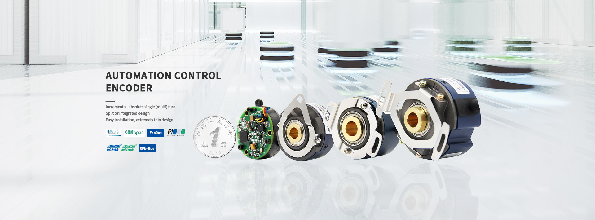
- Precision Measurement and Stability Performance - A New Breakthrough in Rotary Encoder, Angle Encoder, Linear Encoder, and Glass Disk TechnologyPrecision Measurement and Stability Performance - A New Breakthrough in Rotary Encoder, Angle Encoder, Linear Encoder, and Glass Disk Technology In today's rapidly developing technology, the demand for precise measurement and stable performance is becoming increasingly prominent. Encoders, as a precision measurement device, are widely used in various industrial scenarios. Recently, the technological innovation of rotary encoders, angle encoders, and linear encoders, as well as the optimization of glass disc technology, have brought more efficient and accurate solutions to modern industry. As a commonly used measuring device, the stability and accuracy of rotary encoders have always been a focus of attention in the industry. Recently, new rotary encoders have attracted widespread market attention due to their excellent rotational measurement performance and long lifespan. This encoder adopts advanced sensing technology, which can monitor the rotation angle in real-time and provide accurate data feedback. It is widely used in fields such as machinery, automation, and control systems. Similar to rotary encoders, angle encoders also focus on monitoring rotational motion. However, angle encoders are more focused on providing higher precision measurements. The new angle encoder adopts a unique algorithm and sensor design, which can achieve more accurate angle measurement. This breakthrough not only improves measurement accuracy, but also greatly expands the application range of angle encoders, providing reliable solutions for high-precision fields such as aerospace, medical, and energy. Linear encoders focus on processing object motion along paths or lines. This encoder uses advanced sensor technology to accurately measure the motion or distance between two points. Whether for fixed length cutting applications or precise linear motion control, the new linear encoder can provide stable and reliable performance. In addition, its compact design and strong adaptability enable it to operate stably in various complex environments. At the same time, the optimization of glass disk technology has also brought new breakthroughs to encoders. Glass discs are renowned for their high precision, high stability, and long lifespan, making them an ideal choice for encoders. The new glass disc adopts advanced materials and manufacturing processes, which not only improves the flatness and accuracy of the disc surface, but also enhances its wear resistance and impact resistance. These optimizations enable the glass disc to maintain stable performance in various harsh environments, providing more reliable support for the encoder. Overall, breakthroughs in new rotary encoders, angle encoders, linear encoders, and glass disc technologies have brought more efficient and accurate measurement solutions to modern industry. Their widespread application not only improves production efficiency, but also promotes technological progress in various industries. In the future, with the continuous development of technology, these encoder products will continue to play a greater role and make greater contributions to human technological progress.
2023 06/30
- Photoelectric encoder characteristicsThe photoelectric encoder works as a photoelectric encoder, which is a sensor that converts the mechanical geometric displacement on the output shaft into a pulse or digital quantity through photoelectric conversion. This is currently the most widely used sensor. The optical encoder consists of a grating disk and a photodetector. The grating plate is opened on a certain diameter of a circular plate and several rectangular holes are equally divided. Since the photoelectric encoder and the motor are coaxial, when the motor rotates, the grating disk rotates at the same speed as the motor, and a detection device composed of an electronic component such as a light emitting diode detects and outputs a plurality of pulse signals. The schematic diagram thereof is shown in FIG. 1; The number of output pulses of the photoelectric encoder can reflect the current motor speed. In addition, to determine the direction of rotation, the encoder can also provide two pulse signals with a phase difference of 90o. According to the detection principle, encoders can be classified into optical, magnetic, inductive and capacitive. According to its calibration method and signal output form, it can be divided into incremental, absolute and hybrid. 1.1 Incremental Encoder Incremental Encoder directly outputs the three groups of square-wave pulses A, B and Z phases using the photoelectric conversion principle; A, B two groups of pulses have a phase difference of 90o, so that the rotation direction can be easily judged. Phase Z is one pulse per revolution for reference point positioning. Its advantage is that the principle of the structure is simple, the mechanical average life can be more than tens of thousands of hours, anti-interference ability, high reliability, suitable for long-distance transmission. The disadvantage is that the absolute position information of the shaft rotation cannot be output. 1.2 Absolute encoder Absolute encoder is a sensor that outputs digital data directly. There are several concentric code channels in the radial direction on its circular code wheel. Each channel consists of light-transmitting and opaque sectors. The number of sectors adjacent to the code channel is a double relationship. The number of code channels on the code board is the number of bits of its binary digits. On one side of the code disk is a light source, and on the other side, there is a photosensitive element for each code channel; When the code wheel is in different positions, each photosensitive element converts a corresponding level signal according to whether it is illuminated or not, forming a binary number. The characteristic of this type of encoder is that it does not require a counter. A fixed digital code corresponding to the position can be read out at any position on the spindle. Obviously, the more code channels, the higher the resolution. For an encoder with N-bit binary resolution, the encoder must have N code channels. At present, there are 16 absolute encoder products in China. Absolute encoders use natural binary or circular binary (Geray code) methods for photoelectric conversion. Absolute encoders and incremental encoders differ in that they are light-transmitting and opaque line patterns on the disk. The absolute encoder can have several codes. The absolute position can be detected based on the code on the readout code. The coding design can use binary code, cyclic code, two's complement and so on. It is characterized by: 1.2.1 The absolute value of the angular coordinate can be read directly; 1.2.2 There is no cumulative error; 1.2.3 Position information will not be lost after the power is cut off. However, the resolution is determined by the number of binary digits, which means that the accuracy depends on the number of digits. There are currently 10 digits, 14 digits, and so on. 1.3 Hybrid Absolute Encoder A hybrid absolute encoder that outputs two sets of information: one set of information used to detect magnetic pole position with absolute information function; the other set is exactly the same as incremental encoder output information. Photoelectric encoder is an angle (angular velocity) detection device. It will input the amount of the angle to the shaft and convert it into the corresponding electric pulse or digital quantity using the photoelectric conversion principle. It has the advantages of small size, high precision, reliable work, digital interface, etc. . It is widely used in devices and devices that require angle detection such as CNC machine tools, rotary tables, servo drives, robots, radars, and military target measurements.
2023 06/29
- The principle and use of incremental encoderThe principle and use of incremental encoder An encoder is a device that converts an angular displacement or a linear displacement into an electrical signal. According to the working principle, the encoder can be divided into two types: incremental (SPC) and absolute (APC). The incremental encoder converts the displacement into a periodic electrical signal, which is then converted into a counting pulse, and the number of pulses is used to represent the magnitude of the displacement. Here is some introduction to incremental encoders. 1. working principle The working principle of the photoelectric incremental encoder is as follows: the pulse code disc rotating together with the rotating shaft has a uniformly engraved grating, and a plurality of transparent sections and shading sections are evenly distributed on the code disc. Incremental encoders do not have a fixed starting zero. The output is a pulse proportional to the increment of the corner. A counter is required to count the number of pulses. Each time a light transmissive area is rotated, a pulse signal is sent, the current value of the counter is incremented by 1, and the count result corresponds to the increment of the corner. Incremental encoders are simple to manufacture, inexpensive, and sometimes used to measure absolute corners. 2. Incremental encoder classification (1) A single-channel incremental encoder has only one pair of optocouplers inside, and only one pulse sequence can be generated. (2) The AB phase encoder has two pairs of photocouplers inside, and outputs two sets of pulse sequences with a phase difference of 90°. The lead and lag relationship of the two pulses in the forward and reverse directions is just the opposite. As can be seen from the figure below, at the rising edge of the B-phase pulse, the level of the A-phase pulse is reversed when the forward and reverse are reversed. Therefore, using the AB-phase encoder, the PLC can easily recognize the direction of rotation of the shaft. When it is necessary to increase the accuracy of the measurement, the 4th frequency mode can be used, that is, the rising edge and the falling edge of the A and B phase waveforms respectively, and the resolution can be increased by 4 times, but the high frequency of the zui of the measured signal is correspondingly reduced. (3) In addition to the two pairs of optocouplers with dual-channel incremental encoders, the three-channel incremental encoder has one light-transmitting section in the other channel of the pulse code disc, one revolution per revolution, and output 1 One pulse, called the Z-phase zero pulse, is used as the system clear signal, or the origin of the coordinates to reduce the accumulated error of the measurement. The advantages of the incremental encoder are simple structure, long average life, strong anti-interference ability and high reliability, which is suitable for high-precision positioning control for continuous operation. The disadvantage is that the absolute position information of the shaft rotation cannot be output. 3. Encoder selection First, the type of encoder is selected according to the measurement requirements. The number of pulses per revolution of the incremental encoder is equal to the number of lines of its grating. The number of encoder lines should be determined according to the speed measurement or positioning requirements and the encoder speed. The encoder is mounted on the motor shaft or mounted on a shaft after deceleration. The encoder speed is very different. It should also be considered whether the high frequency of the zui of the pulse it emits is within the range allowed by the PLC's high-speed counter. 3. Coordination problem between encoder and PLC high-speed counter Taking the S7-200 as an example, when using a single-channel incremental encoder, the single-phase up/down counter mode (mode 0~5) of the high-speed counter can be selected, which can be subdivided into yes/no external direction input signals, with / No reset input and with/without start input signal. When using the AB phase encoder, the high-speed counter should select the A/B phase quadrature counter mode (modes 9 to 11), which can be used to count up during forward rotation and count down during reverse rotation. 4. How to judge whether the AB phase encoder is forward or reverse? The high-speed counter of the S7-200 uses the current count direction status bit in the SM area to indicate the direction of rotation of the encoder. If the period of the encoder output pulse is greater than twice the scan cycle time of the PLC, the direction of the encoder rotation can be judged by judging the 0, 1 state of the A phase pulse signal on the rising edge of the B phase pulse.
2023 06/14
- The principle and use of incremental encoderThe principle and use of incremental encoder An encoder is a device that converts an angular displacement or a linear displacement into an electrical signal. According to the working principle, the encoder can be divided into two types: incremental (SPC) and absolute (APC). The incremental encoder converts the displacement into a periodic electrical signal, which is then converted into a counting pulse, and the number of pulses is used to represent the magnitude of the displacement. Here is some introduction to incremental encoders. 1. working principle The working principle of the photoelectric incremental encoder is as follows: the pulse code disc rotating together with the rotating shaft has a uniformly engraved grating, and a plurality of transparent sections and shading sections are evenly distributed on the code disc. Incremental encoders do not have a fixed starting zero. The output is a pulse proportional to the increment of the corner. A counter is required to count the number of pulses. Each time a light transmissive area is rotated, a pulse signal is sent, the current value of the counter is incremented by 1, and the count result corresponds to the increment of the corner. Incremental encoders are simple to manufacture, inexpensive, and sometimes used to measure absolute corners. 2. Incremental encoder classification (1) A single-channel incremental encoder has only one pair of optocouplers inside, and only one pulse sequence can be generated. (2) The AB phase encoder has two pairs of photocouplers inside, and outputs two sets of pulse sequences with a phase difference of 90°. The lead and lag relationship of the two pulses in the forward and reverse directions is just the opposite. As can be seen from the figure below, at the rising edge of the B-phase pulse, the level of the A-phase pulse is reversed when the forward and reverse are reversed. Therefore, using the AB-phase encoder, the PLC can easily recognize the direction of rotation of the shaft. When it is necessary to increase the accuracy of the measurement, the 4th frequency mode can be used, that is, the rising edge and the falling edge of the A and B phase waveforms respectively, and the resolution can be increased by 4 times, but the high frequency of the zui of the measured signal is correspondingly reduced. (3) In addition to the two pairs of optocouplers with dual-channel incremental encoders, the three-channel incremental encoder has one light-transmitting section in the other channel of the pulse code disc, one revolution per revolution, and output 1 One pulse, called the Z-phase zero pulse, is used as the system clear signal, or the origin of the coordinates to reduce the accumulated error of the measurement. The advantages of the incremental encoder are simple structure, long average life, strong anti-interference ability and high reliability, which is suitable for high-precision positioning control for continuous operation. The disadvantage is that the absolute position information of the shaft rotation cannot be output. 3. Encoder selection First, the type of encoder is selected according to the measurement requirements. The number of pulses per revolution of the incremental encoder is equal to the number of lines of its grating. The number of encoder lines should be determined according to the speed measurement or positioning requirements and the encoder speed. The encoder is mounted on the motor shaft or mounted on a shaft after deceleration. The encoder speed is very different. It should also be considered whether the high frequency of the zui of the pulse it emits is within the range allowed by the PLC's high-speed counter. 3. Coordination problem between encoder and PLC high-speed counter Taking the S7-200 as an example, when using a single-channel incremental encoder, the single-phase up/down counter mode (mode 0~5) of the high-speed counter can be selected, which can be subdivided into yes/no external direction input signals, with / No reset input and with/without start input signal. When using the AB phase encoder, the high-speed counter should select the A/B phase quadrature counter mode (modes 9 to 11), which can be used to count up during forward rotation and count down during reverse rotation. 4. How to judge whether the AB phase encoder is forward or reverse? The high-speed counter of the S7-200 uses the current count direction status bit in the SM area to indicate the direction of rotation of the encoder. If the period of the encoder output pulse is greater than twice the scan cycle time of the PLC, the direction of the encoder rotation can be judged by judging the 0, 1 state of the A phase pulse signal on the rising edge of the B phase pulse.
2023 05/25
- Video encoder new technology development trendVideo encoder new technology development trend [Market analysis] The LAN-based SD video system evolved in two directions, one is the LAN high-definition video system, and the other is the Internet and mobile Internet standard definition video system, which requires a new generation of video systems must balance high-definition resolution, support more Streaming and multi-protocol support for live, on-demand, on-demand applications across LAN, Internet and mobile internet. The Internet has completely changed people's lives and communication methods. From Web1.0 to Web2.0 to search engines, people can first obtain text and image information through the Internet. In recent years, video file information can also be obtained through the Internet and Others share their uploaded video clips, such as Tudou, Youku, etc. It is foreseeable that in the near future, accessing online real-time video information via the Internet or publishing shared online real-time video information will become a new market growth point. Web-based real-time video applications have been active in the traditional vertical industry market, and online video is an old but challenging technology area: The video conferencing system was born to meet the multi-point full-duplex video communication. The video conferencing camera, the video conferencing terminal and the multi-point access unit constitute a multi-point video duplex communication system. People can use a dedicated system and a dedicated network to off-site. Convening meetings, the emergence of such a system can shorten the cost of people going to meetings in different places, reduce the frequency of travel, and shorten the decision-making time. Such as Polycom's video conferencing system, Cisco's telepresence system belongs to this type of system; The video surveillance system was born to meet the video information of multiple remote locations. Through the network camera, storage server and forwarding server, a typical video surveillance system can be constructed. Through the video wall of the client or monitoring center, View video information of multiple remote spaces, used in emergency command, security monitoring, intelligent transportation and other occasions; The video recording and broadcasting system is designed to meet the needs of multiple users watching one or several video sources at the same time. The camera, recording server and client can construct a typical video recording and broadcasting system, multiple clients. You can log in to the recording server to watch online video or on-demand video. This system is mainly used in recording and broadcasting classrooms in the education industry, digital operating rooms in the medical industry, and digital court trials in the public security industry. The above three typical systems abstract the model: look at one point, look at multiple points, and see more points. In order to meet the technical needs of these three basic models and the technical needs of the Internet, a device is needed. It can be applied to both existing systems and Internet applications, so that the integrator's existing services can be upgraded to high-definition video using proprietary protocols on the private network, and can be fully and quickly advanced to the Internet using Flash streaming media technology. The market, based on Aowei Video's latest third-generation embedded processor system framework technology, the AURORA series network encoder products and the MAYA series network camera products are the only embedded coding devices on the market that support multi-mode protocols. The design concept is to provide integrator users with three dimensions of unification: The first is the unification of the high-definition video resolution dimension, which is aimed at the difference between the SD video system and the HD video system and the private network and Internet bandwidth resources. Vivid's 1080P HD products are available in resolutions from 320 x 240 to 1920 x 1080 From 10 frames per second to 60 frames per second, the code rate supports from 100kbps up to 20Mbps. The video uses the most advanced and efficient H.264 High Profile compression algorithm. The audio uses two-channel stereo AAC or MP3 compression. The algorithm can greatly save bandwidth and improve the subjective quality of audio and video. The second is the unification of digital-analog interfaces. At present, the number of analog source devices in the market is still huge, and high-definition video uses digital interfaces, interlaced video and Progressive video still coexists, which will inevitably require integrators and end users to purchase multiple encoding devices for different sources to access the network, while Avitech's AUR3G7KE series products target this multi-standard digital model. The coexistence of the interface gives a perfect answer, which allows the user system to support analog composite video (CVBS and SVideo), analog component video (Component), VGA analog graphics interface (RGBHV), DVI- with zero changes. D digital graphics interface, HDMI multimedia high-definition digital interface and access to multiple signal sources including SDI/HDSDI/3GSDI high-definition serial digital interface Greatly protect the customer's investment, and help integrators to meet the needs of end users and systems with the fastest speed and zero replacement cost; the third is the unification of multi-mode access protocols, Aowei video equipment can support four at the same time Access protocols, including TS transport stream protocol, RTSP real-time streaming media transport protocol, Flash RTMP protocol and AVST proprietary protocol, wherein the proprietary protocol is applicable to vertical industry integrators' existing recording and broadcasting platform software, and AVST provides for private protocols. Complete PC-side SDK development kit and technical support services, SDK development kit supports high-efficiency 1080P60 decoding and display library, support for network preview, storage, playback, forwarding and other core media layer functions; TS transport stream protocol is mostly used for broadcasting and television System platform, STB system-based information publishing platform and various live broadcast systems; RTSP real-time streaming media transfer protocol is mostly used for private network systems based on Apple's Darwin streaming media server or Apple's various terminal devices such as iPhone, iPad and MAC computer; RTMP real-time information protocol is the core part, Aowei video company is embedded The Flash Media Server software protocol stack was successfully developed on the system, which allows users to directly view the device's Flash video directly without a plug-in using a browser that supports Flash. The encoding device also supports direct push of Flash audio and video streams to the Flash stream. Media servers, including Adobe's FMS server, open source version of Red5 server and commercial WOWZA server. This article refers to the address: http:// [Encoder Features] AUR3G7KE is the main product of Aowei AURORA's third-generation encoder product line. AUR3G7KE adopts intelligent interface technology. The device supports power-on automatic identification of input signal format. At the same time, the device can track and synchronize the input signal at the same time. That is, if the signal detected by the device is 1080P60 when the power is turned on, when the code transmission is performed, the signal source becomes 720P60, and the encoder can automatically detect the change of the signal source without any restart or manual intervention, and correspondingly The adjustment, the network transmission until the format and resolution of the decoding display will be changed synchronously, greatly improving user experience and system intelligence. AUR3G7KE supports four-mode network transmission protocol, providing customers with complete SDK and protocol documentation. It can support standard RTSP protocol, RTMP protocol, TS protocol and private protocol. It is worth mentioning that when using proprietary protocol, the encoder Working in 1080P30/P60 mode, the system's end-to-end delay is only 110-120ms, which can fully achieve strong real-time effects. The AUR3G7KE product line supports innovative windowing video processing technologies, including hardware scaling, deinterlacing (interleaving), frame rate conversion (upconversion and downconversion), resolution and frame rate conversion techniques that can handle 576i The /480i/1080i interlaced video to progressive function converts low-definition video images into high-definition progressive video images. The window-opening technology allows users to customize a variety of non-standard video image formats. AUR3G7KE adopts a variety of advanced image processing technologies, including multiple target area coding techniques (Multi-ROI-Coding), which can perform priority quality coding for multiple regions of interest set by users. Under the premise, the image quality of the ROI area is greatly improved; at the same time, the product also supports adaptive scene switching, and parameters are optimized for various typical user scenarios, so that AUR3G7KE is in movie mode, desktop mode, text mode, Typical application scenarios such as endoscope mode, recording mode, live mode, conference mode, and monitoring mode all show optimal performance. AUR3G7KE supports full HD real-time dual stream output. It can support H.264-HP standard of 720x576p25 in secondary stream while the main stream supports 1920x1080p25 H.264-HP standard, and the primary and secondary streams can independently set the bit rate. And H.264 encoding grade (BP/MP/HP) and network transmission protocol, the typical application can use RTSP protocol or proprietary protocol in the local area network (special network) with 1080P full HD main stream to work at 4-8Mbps rate In the Internet (public network) using RTMP protocol with 720x576p25/320x240p30 sub-stream to work at 200-500kbps code rate, to meet the "local area to see clear, the Internet to see" market demand. Figure-1 Typical application of HD video encoder [System Integration Case] Avitech's third-generation embedded processor system framework software development kit (AVSolution Technology Co., Ltd. Embedded-Processor-System-Framework III, hereinafter referred to as SDK3.0) is a set of high-performance multimedia middleware based on IP network. Software, based on Ovi's third-generation embedded processor system framework technology, SDK3.0 can support all of Ovid Video's EPSF-III series of embedded products, including the AURORA series of embedded HD encoders, MAYA series network HD cameras, CERES series of HD decoders and servers, the goal is to build a full-HD audio and video system based on IP across LAN and Internet. Figure-2 SDK3.0 middleware software composition AVST's embedded devices include two product lines, AURORA HD encoder and MAYA HD network camera, including multi-stream multi-protocol applications, SDK 3.0 for the standard development of the interconnection protocol MPEG-TS protocol, RTSP protocol, RTMP protocol The device control interface calling routine is used for system integration using an existing system or an open source/commercial streaming media server, such as using MPEG-TS protocol and multicast function to realize television signal monitoring of radio and television systems, and realizing remote multimedia information distribution. Such as the use of RTSP protocol and Darwin server to achieve digital court and remote interrogation system integration, such as using RTMP protocol and FMS4.5 or Red5 server to achieve Internet live broadcast and mobile Internet live broadcast system integration; for Ovid video's proprietary high-performance interconnect protocol provides complete The multimedia middleware software can quickly develop or deploy recording, live broadcast, on-demand server, forwarding server, client and digital matrix to support multi-screen HD TV wall display. Figure-3 Typical system integration of SDK3.0 middleware software [to sum up] Mr. Zheng Xiaolong, Marketing Development Manager of Texas Instruments, said: "Texas Instruments (TI) is committed to providing customers with superior solutions to help them cope with various design challenges. We are very happy to see Ovi Video adopt TI's DaVinci technology introduces a series of IP-based 1080P HD video products and system-level solutions, which can help integrators and engineers quickly complete system integration and system deployment. In the future, TI and Ovid will continue to deepen. The cooperation, I believe that TI's powerful video processor platform can bring greater success to Ovid Video and more innovative breakthroughs in the digital video processing industry." Mr. Wang Fuyu, general manager of Ovi Video, said: [Information technology can reduce the cost of communication between people and reduce the cost of acquiring unknown information. As long as it is a technology that can reduce the cost of communication or the cost of acquiring unknown information, it can always be successfully transformed. For the product, to form a new market, to promote the development of productivity and the progress of human civilization. The transformation of the industrial chain is inevitable, both in the consumer market and the industry market, and the emerging Internet video technology is rapidly integrating with the traditional industry market. Aowei Video focuses on the R&D and accumulation of core technologies for high-performance video products. It can provide high-quality network video products and system products for integrators and engineering customers in many vertical industries. We are willing to work closely with our customers to open them together. A new chapter in the digital video market."
2023 05/25
Email to this supplier